Perinet periMICA
Perinet periMICA uses LXC containers, so the container must be downloaded and installed manually.
installing logiccloud Control
The periMICA has its own interface that you can use to install containers. You can find this via the IPv6 specified on the device, for example https://periMICA-b3665.local. Once you have logged in, you can install a new container in the lower area under Installation. You can download the container here:
logiccloud Control for Perinet periMICA
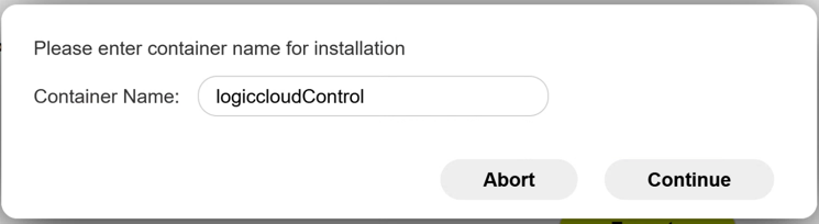
During the installation, you still need to assign the name for the container:
Once the installation is complete, you will find the new container in the main menu:
To start this, right-click on the container and select Start. As soon as the container is highlighted green, it is started. Click on the container to open the container interface.
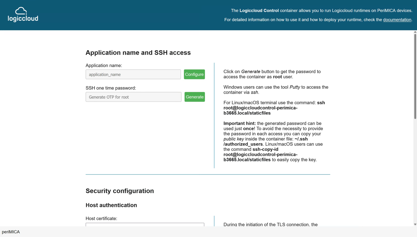
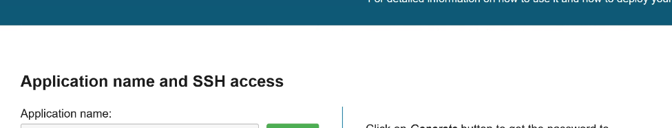
You can make settings here if you want to connect to the container via SSH, for example.
To access the interface for connecting the device to logiccloud, simply click on the button at the top. Alternatively, you can access the interface via the container IP /control, in our example this is: https://logiccloudcontrol-perimica-b3665.local/control/.
Configuring the MQTT broker on periMICA
So that we can use the data from the periNODE in logiccloud, we must first configure it. If the MQTT container has not yet been started on the periMICA, we first do this by right-clicking and Start.

We then open the MQTT container and deactivate MQTT over TLS and mTLS authentication for this demo. We can freely assign the Application name, here for example demo. Finally, we click on push configuration.
Configure periNODE with MQTT
Next, we need to access the periNODE's web interface. We can access this via the IP specified on the periNODE, in our example https://perinode-hihsd.local/. Here we can directly see the current value of the sensor. We can now configure the MQTT connection under the Configuration tab. To do this, we enter the IP address of the periMICA, in our example mqtt://mqtt-perimica-b3665.local. The Application name must match the name previously assigned in the MQTT configuration, in our example demo. We give the element name the value distance. We then click on push configuration.

If we now connect to the MQTT broker with the MQTT Explorer, for example, we can see the data that the periNODE sends.
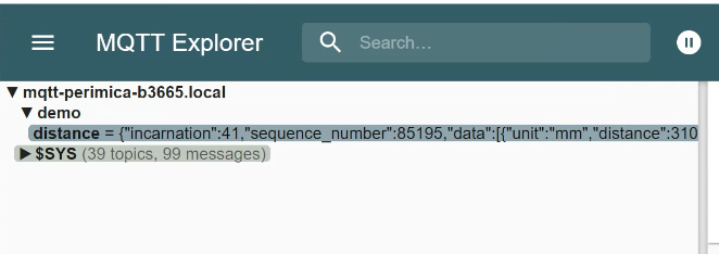
The payload looks like this:
{
  "incarnation":41,
  "sequence_number":85229,
  "data":[
    {
      "unit":"mm",
      "distance":310.0
    }
  ]
}
Connect periMICA with logiccloud
If you do not yet have an account, you can register here: create logiccloud account.
After logging in, you will find the Devices tab in the main navigation on the left-hand side. You can now add your device there. To do this, click on the + icon and give your device a name, select the manufacturer and enter the corresponding type. You can also add the serial number and a description. For a better overview of several devices, you can also assign tags.

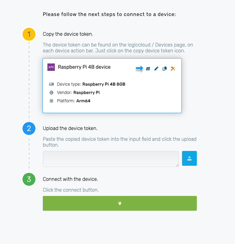
Once you have created the device, you can only copy the device token for activation. To do this, click on the Copy Device Token Icon.

Activate logiccloud Control
The next step is to activate the device. To do this, please go back to the logiccloud container web interface on the periMICA. There you will be guided through the installation wizard and can insert the copied token. The device is then linked to the logiccloud portal and you can create the runtime.
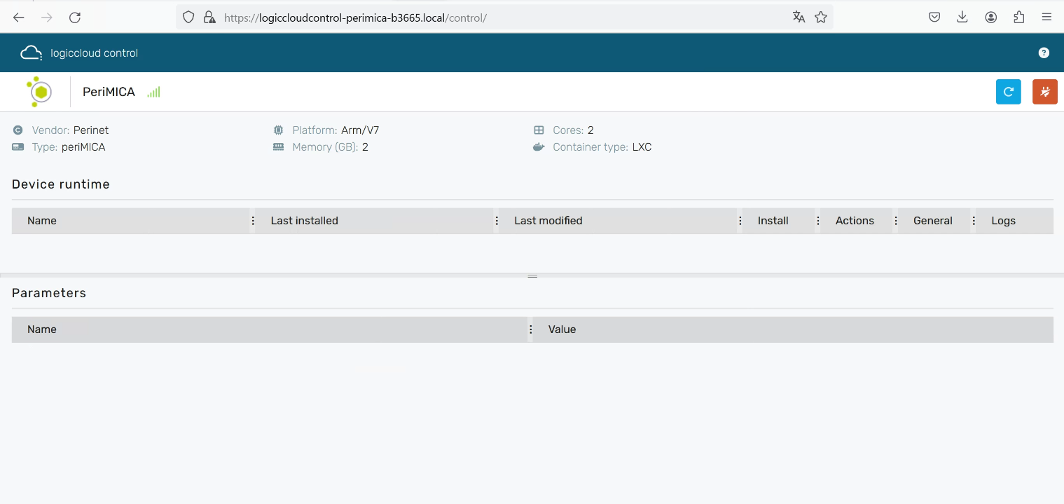
As soon as the installation is complete, you will be redirected to the logiccloud control interface:
First project with logiccloud
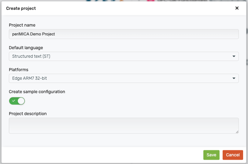
We create a new project under Projects and give it a name, select ARM v7 32-bit as the platform and leave the Sample Configuration selected.
Then we open the project and select the POU my_program. We can now create our program here. We will connect a distance sensor periNODE and read out the data via MQTT. In addition, an indicator light should light up depending on the distance.
VAR_INPUT
    distance: REAL;
    distanceSetpoint: REAL;
END_VAR

VAR_OUTPUT
    lamp: BOOL;
END_VAR

IF distance < distanceSetpoint THEN
    lamp := TRUE;
ELSE
    lamp := FALSE;
END_IF
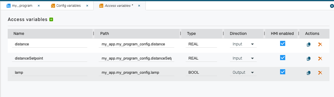
We save the project via STRG + S / CMD + S. Next, we need to define the Access variables.
In the Config Variables we have to delete the two example variables.
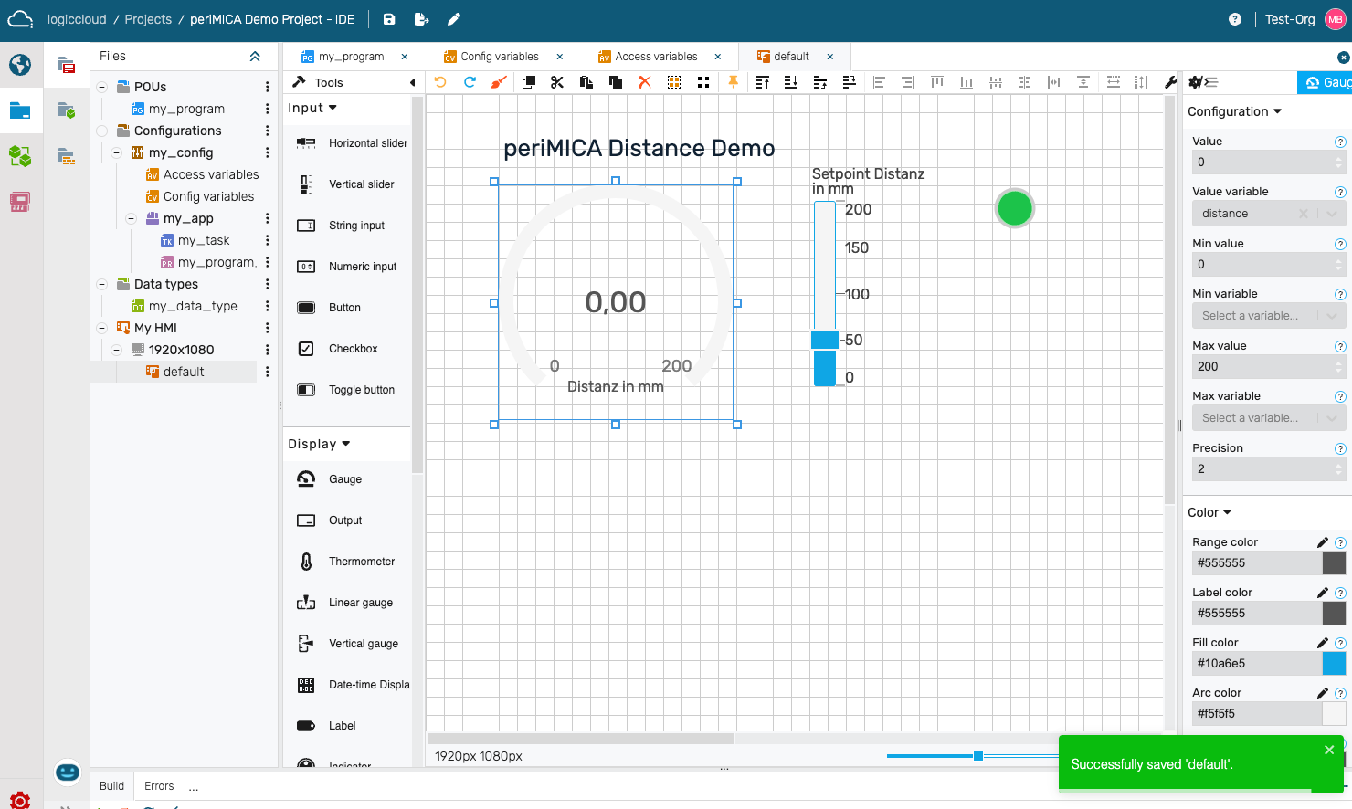
Next, we can design the HMI. To do this, we select the default page within the 1920x1080 resolution and remove all elements.
We add a gauge element and connect it to the distance variable via the Value Variable entry. In addition, we set Max value to 200 and the Label to Distance in mm.
Next, we add a Vertical Slider element, connect it to the distanceSetpoint variable and set Max value to 200 and the Label to Setpoint distance in mm.
Finally, we add an Indicator element, connect it to the lamp variable and set Threshold to 1.
Once all the changes have been saved, we can start a build using the green Start icon.

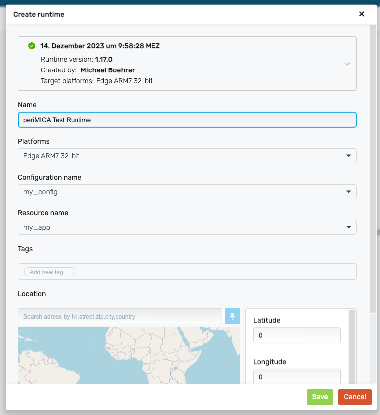
As soon as the build has run, we can create a runtime. To do this, we navigate to Project Runtimes and create a new runtime by clicking on the + icon.

We assign a name Name, the platform for which our project was compiled Edge ARM7 32-bit, select the build that we have just created. You can also add Tags, a Location and a description Description. Then click on Save.
Configure MQTT connection
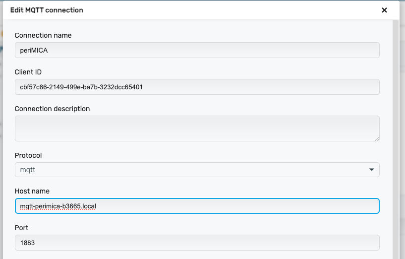
We then select the runtime and go to the connection settings for the connector for MQTT. By right-clicking on MQTT, we can create a Custom Connection and enter the URL for the MQTT broker on the periMICA, in our example Protocol: mqtt, Host: mqtt-perimica-b3665.local, the port is 1883. We do not need a user name and password for our demo.
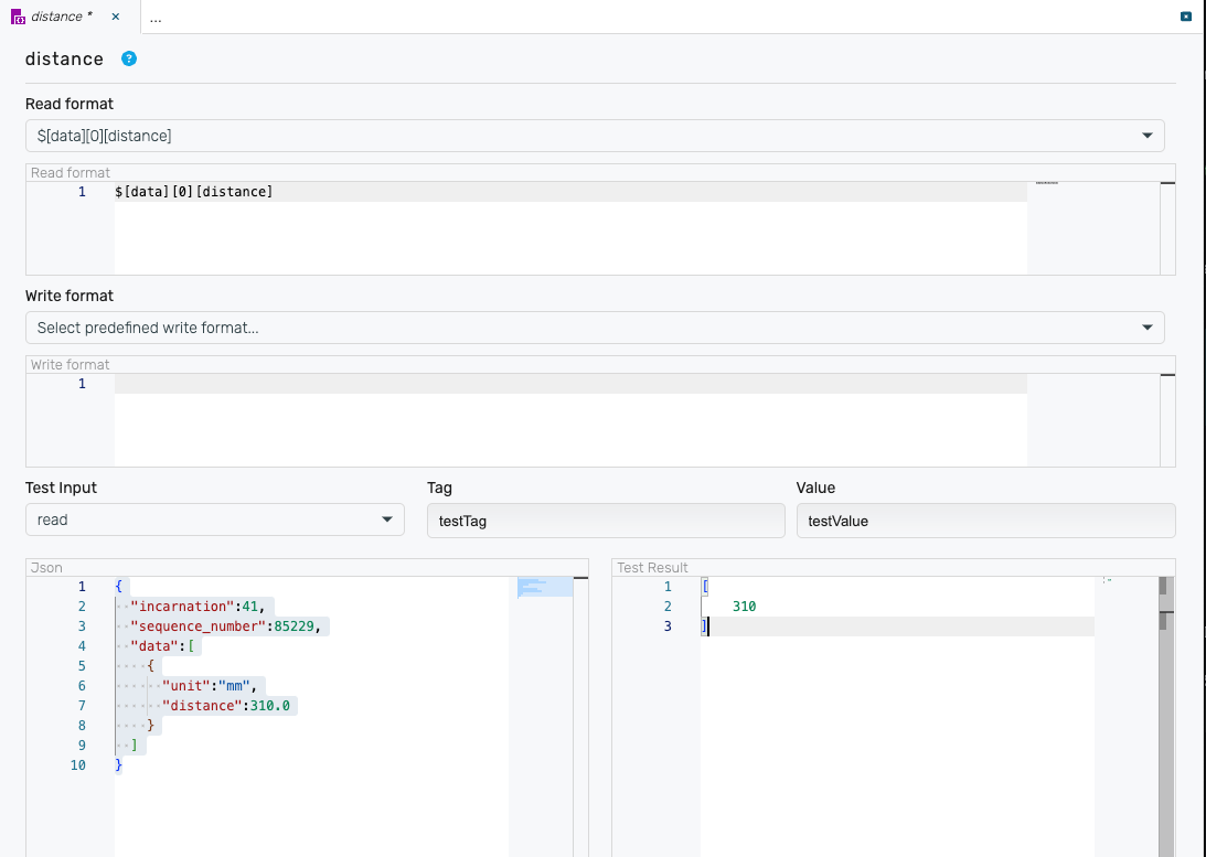
We can create a new payload by right-clicking on the connection and giving it the name distance.

We can then define the payload and specify the structure. To do this, we copy the payload from above into the lower left test field. Under Readformat we now have to map the structure so that the distance value can be read. In the bottom right-hand window, we can see the result of the input above. After the input, we save the changes.
# Read Format
$[data][0][distance]
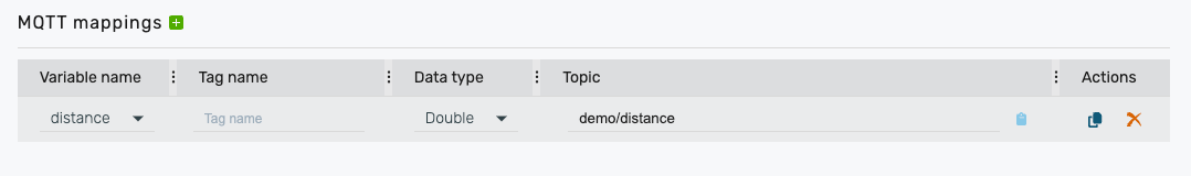
Finally, we need to go to the payload mapping and map the variable. To do this, we go to distance mapping and add the variable distance. The Data Type is double and the topic is demo/distance as in the MQTT Broker above.
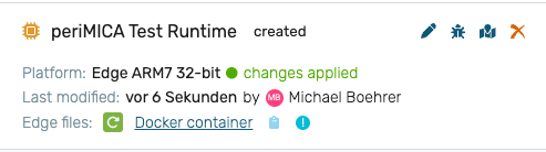
Update runtime
We need to update the runtime with the changes. To do this, we click on the green button to update the edge files. As soon as changes applied is displayed, we can deploy the runtime.
Configure runtime container
We still need to configure the logiccloud control container so that the MQTT assignments are correct. To do this, we need to connect to the container via SSH. To do this, we go to the container interface, in our example https://logiccloudcontrol-perimica-b3665.local/ and click on Generate at SSH one time password. Now we can connect to the container with an SSH client, for example Putty, Windows PowerShell or Mac Terminal. The user is root.
# SSH connection via Windows PowerShell or Mac Terminal with container IP and user root
ssh root@logiccloudcontrol-perimica-b3665.local
As soon as we are logged in, we need to create a file with the name of the MQTT broker. We simply do this using the following command. The address of the MQTT broker in our example is mqtt-perimica-b3665.local.
# Create file
touch /logiccloudcontrol-perimica-b3665.local
Deploy runtime
To deploy the runtime, please navigate to Devices in the main menu. If you have not yet created a device, you will find a description here: Create device and install logiccloud control.
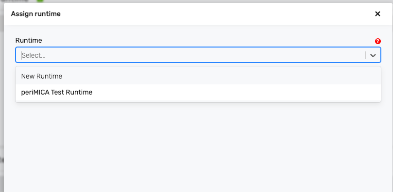
Click on the green + icon to assign a new runtime to your device. To do this, select the corresponding runtime. You can also enter a licence key. If you do not enter a licence key, the Runtime is started with a trial licence and stops automatically after 2 hours. Licences can be obtained via our shop and Sales.
You can now install the Runtime via Install. As soon as the installation is complete, Runtime starts automatically.
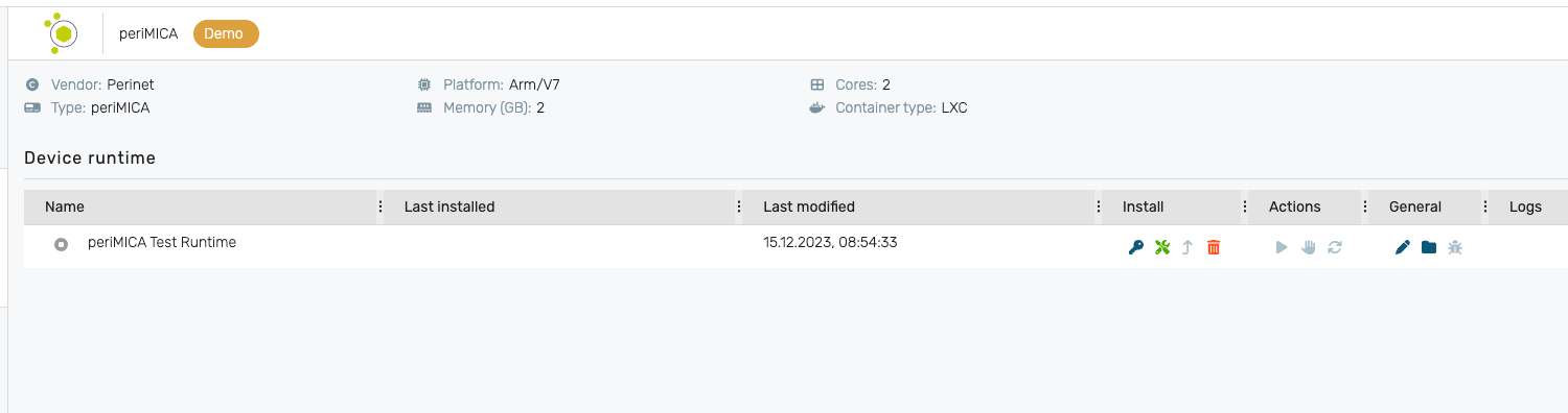
You can now see the runtime that you have deployed on the periMICA. You can now access the runtime via the interface on your device. You can also open it manually via <CONTAINER IP>/hmi, in our example this is https://logiccloudcontrol-perimica-b3665.local/hmi.
